Switch is an electrical component which can make or break electrical circuit automatically or manually. Switch is mainly works with ON (open) and OFF (closed) mechanism. Numerous circuits hold switches that control how the circuit works or actuate different characteristics of the circuit. The classification of switches depends on the connection they make. Two vital components that confirm what sorts of connections a switch makes are pole and throw.
These are classified on based the connections they make. If you were under the impression that switches simply turn circuits on and off, guess again.
The terms pole and throw are also used to describe switch contact variations. The number of “poles” is the number of separate circuits which are controlled by a switch. The number of “throws” is the number of separate positions that the switch can adopt. A single-throw switch has one pair of contacts that can either be closed or open. A double-throw switch has a contact that can be connected to either of two other contacts; a triple-throw has a contact which can be connected to one of three other contacts, etc.
Pole: The amount of circuits controlled by the switch is indicated by poles. Single pole (SP) switch controls only one electrical circuit. Double pole (DP) switch controls two independent circuits.
Throw: The number of throws indicates how many different output connections every switch pole can connect its input. A single throw (ST) switch is a simple on/off switch. When the switch is ON, the two terminals of switch are connected and current flows between them. When the switch is OFF the terminals are not connected, so current does not flow.
4 Types of Switches
Basic types of switches are SPST, SPDT, DPST and DPDT. These are briefly discussed below.
Working of SPST Switch
The Single Pole Single through (SPST) is a basic on/off switch that just connects or breaks the connection between two terminals. The power supply to a circuit is switched by the SPST switch. A simple SPST switch is shown in figure below.
![]()

These types of switches are also called toggle switches. This switch has two contacts one is input and other output. From the typical light switch diagram, it controls one wire (pole) and it makes one connection (throw). This is an on/off switch, when the switch is closed or on then current flows through the terminals and the bulb in circuit will glow. When the switch is open or off then there is no current flow in the circuit.
Working of SPDT Switch
The single pole double throw (SPDT) switch is a three terminal switch, one for input and other two for the outputs. It connects a common terminal to one or the other of two terminals. For using the SPDT as SPST switch then just use the COM terminal instead of other terminals. For instance we can use COM and A or COM and B.
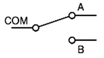
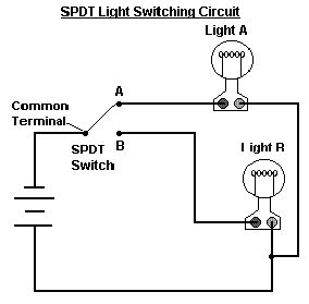
From the circuit, it clearly demonstrates what happens when the SPDT switch is moved back and forth. These switches are used in a three-way circuit to turn a light ON/OFF from two locations, such as from the top and bottom of a stairway. When the switch A is closed then current flows through the terminal and only light A will ON, and light B will OFF. When the switch B is closed then current flows through the terminal and only light B will ON and light A will OFF. Here we are controlling the two circuits or paths via one way or source.
Working of DPST Switch
DPST is abbreviation for double pole, single throw. Double pole means that the unit contains two identical switches, side by side, and operated by one single toggle or lever. This means that two separate circuits are at a time controlled through one push.
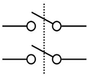
A DPST switch turns two circuits on or off. A DPST switch has four terminals: two inputs and two outputs. The most common use for a DPST switch is to control a 240-volt appliance, where both supply lines must be switched, while the neutral wire may be permanently connected. Here when this switch is toggled current starts flowing through two circuits and interrupted when it is turned OFF.
Working of DPDT Switch
DPDT is a double pole double throw switch; this is equivalent to two SPDT switches. It routes two separate circuits, connecting each of two inputs to one of two outputs. The position of the switch determines the number of ways in which each of the two contacts can be routed.
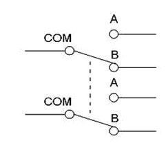
Whether it is in ON-ON or ON-OFF-ON mode they functions like two separate SPDT switches operated by the same actuator. Only two loads can be ON at a time. A DPDT can be used on any application that requires an open and closed wiring system, an example of which is railroad modeling, which makes use of small scaled trains and railways, bridges and cars. The closed allows for the system to be ON at all times while open allows for another piece to be turned ON or activated through the relay.
From the circuit below, connections A, B and C form one pole of the switch and connections D, E and F form the other. Connections B and E are common in each of the poles.
If the positive power supply (Vs) enters at connection B and the switch is set to the top most position, connection A becomes positive and the motor will rotate in one direction. If the switch is set to the lower most position, the power supply is reversed and connection D becomes positive then the motor will rotate in the opposite direction. In the centre position, the power supply is not connected to the motor and it does not rotate. These types of switches are mainly used in various motor controllers where speed of that motor is to be reversed.
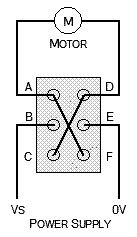
DPDT-Circuit


