A Multimeter is an electronic instrument, every electronic technician and engineer widely used a piece of test equipment. A multimeter is mainly used to measure the three basic electrical characteristics of voltage, current, and resistance. It can also be used to test continuity between two points in an electrical circuit.
The multimeter has multi functionalities, it acts like an ammeter, voltmeter, and ohmmeter. It is a handheld device with positive and negative indicator needles over a numeric LCD digital display. Multimeters can be used for testing batteries, household wiring, electric motors, and power supplies.
Applications:
The applications of ammeter mainly involve various electrical and electronic projects for the purpose of components testing and are also used in different measurement applications in multimeter.
- Temperature and Environmental Applications
-
- Low-cost weather station
- DMM internal temperature
- Voltage Measurements
- High and low-value DC measurement
- Peak to Peak and DC average measurement
- Current Measurements
- DC current measurement
- True RMS AC current
- Resistance Measurement
- Micro ohm meter
- Measuring resistance with constant voltage
- Measuring resistance with constant current
- Time and Frequency measurement
- Fast frequency
- Time measurement
Types of Multimeters:
There are different types of multimeters like
- Analog,
- Digital and
- Fluke multimeters.
How to Use a Digital Multimeter?
Digital Multimeter is a device that has two words in its name: Digital and Multimeter. The first word – digital – indicates that the meter has a digital or liquid crystal display while the next word – multimeter – indicates that this single device can be used for multipurpose i.e. to measure more than one parameter. A typical digital multimeter will be as shown by Figure 1 and comprises of selection switch, display, ports, and probes as its major parts.
Here the probes are to be inserted into appropriate ports and are to be connected across the parameter which needs to be inspected. Meanwhile one should ensure that the selection switch is to be kept at the position which is appropriate for the measurement. When done so, the multimeter displays the value of the parameter which is being analyzed.
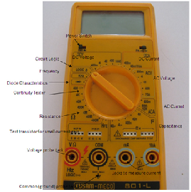
Generally, digital multimeters are used to measure three important parameters viz., current, voltage, and resistance. Apart from these, they can also be used to perform special functions like diode check, capacitance measurement, Transistor hFE or DC current gain, frequency measurement, and continuity check.
Block Diagram
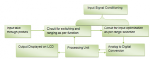
The block diagram shown above gives an overview of the working of the multimeter. Taken through the probes, the input is analog and enters the internal circuitry in form of a wave. The input signal is first conditioned where-after it proceeds to its respective measurement circuitry. Further, it is optimized for its range selection and sent to an analog to digital converter. Analog to digital converters can be of various types depending upon the capabilities of the multimeter and the manufacturer involved. In order to convert the signal, the ADC takes samples of the analog wave. To ensure signal reconstruction, the rate of sampling should be at least twice the frequency of the analog signal.
Most of the ADC used in multimeters follows the dual-slope integration method in which the digital signal is compared to a reference. Their output goes to a successive approximation register (SAR) which sends the final output to the processing unit and balances the reference signal for optimized comparison. The clock input is needed for the SAR counter which is provided by a crystal oscillator. The processing involved in multimeters is usually limited to summing up the pulses and is an integrator circuit.
After analog to digital conversion, the resultant is sent to the processing unit which takes the values, decodes their magnitude, and sends them to the LCD.
After switching the instrument on, the user rotates the knob to the desired measuring function and its range. Corresponding to the function and range selection, concentric rings of the PCB get shorted. This in turn activates that section of the PCB which is responsible for carrying out measurements in that range. Since it is a digital measuring instrument, an Analog to Digital Converter is extensively used to convert the measurements into discrete values.
Except for current, most of the measurements are based on voltage. For instance, while measuring resistance, a small amount of current is sent across the terminals of the DuT. The voltage drop generated is taken as input and is divided by the current by the internal circuitry to determine the resistance.
Multimeters are into electronic measurement purposes for long and are expected to stay for long and get more modifications of measuring quantities. Analog multimeters were initially in trend but required calibration and human error often caused errors in measurements. With digital measurements, results are not only more accurate but can also be resolved to a high level. From voltage to currents, digital multimeters can now even measure temperature, capacitance and can now have RS232 connectors for communication to smarter machines. With newer designs rolling out every day and specialized ICs being made for each and every conceivable measurement, innovative developers continue to put more functionality into the cramped corners of the multimeter while operating at nominal power conditions and costs.
DMM is a measuring instrument
- An ammeter measures current
- A voltmeter measures the potential difference (voltage)
between two points
- An ohmmeter measures resistance
- A multimeter combines these functions, and possibly some additional ones as well, into a single instrument
- Voltmeter
- Parallel connection
- Ammeter
- Series connection
- Ohmmeter
- Without any power supplied
- Adjust range (start from highest limit if you don’t know)
Ammeter Connection

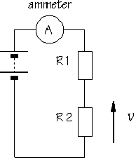

- Break the circuit so that the ammeter can be connected in series
- All the current flowing in the circuit must pass through the ammeter
- An ammeter must have a very LOW input impedance
Voltmeter Connection
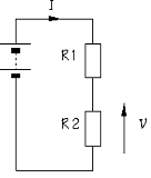


- The voltmeter is connected in parallel between two points of the circuit
- A voltmeter should have a very HIGH input impedance
Ohmmeter Connection
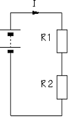
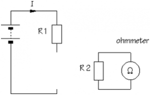
- An ohmmeter does not function with a circuit connected to a power supply
- Must take it out of the circuit altogether and test it separately


