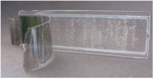
The LCD screen is an electronic display module, it can be used in a wide range of applications. The basic module of the LCD is a 16×2 LCD display and is very frequently used in various electronic circuits and well devices.
Construction and Working Principle of LCD Display
What is an LCD(Liquid Crystal Display)?
A liquid crystal display or LCD draws its definition from its name itself. It is a combination of two states of matter, the solid and the liquid. LCD uses a liquid crystal to produce a visible image. Liquid crystal displays are super-thin technology display screens that are generally used in laptops, computer screens, TVs, cell phones, and portable video games. LCD technologies allow displays to be much thinner when compared to cathode-ray tube (CRT) technology.
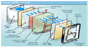
Liquid crystal display is composed of several layers which include two polarized panel filters and electrodes. LCD technology is used for displaying the image in notebooks or some other electronic devices like mini computers. Light is projected from a lens on a layer of liquid crystal. This combination of colored light with the grayscale image of the crystal (formed as electric current flows through the crystal) forms the colored image. This image is then displayed on the screen.
An LCD is either made up of an active matrix display grid or a passive display grid. Most of the smartphones with LCD display technology uses active matrix display, but some of the older displays still make use of the passive display grid designs. Most electronic devices mainly depend on liquid crystal display technology for their display. The liquid has the unique advantage of having low power consumption than the LED or cathode ray tube.
A liquid crystal display screen works on the principle of blocking light rather than emitting light. LCDs require a backlight as they do not emit light by them. We always use devices that are made up of LCD displays which are replacing the use of cathode-ray tubes. Cathode ray tube draws more power compared to LCDs and is also heavier and bigger.
How LCDs are Constructed?
LCD Layered Diagram
Simple facts that should be considered while making an LCD:
- The basic structure of LCD should be controlled by changing the applied current.
- We must use polarized light.
- Liquid crystal should able be to control both of the operations to transmit or can also be able to change the polarized light.
As mentioned above that we need to take two polarized glass pieces filter in the making of the liquid crystal. The glass which does not have a polarized film on the surface of it must be rubbed with a special polymer which will create microscopic grooves on the surface of the polarized glass filter. The grooves must be in the same direction as the polarized film. Now we have to add a coating of pneumatic liquid phase crystal on one of the polarizing filters of the polarized glass. The microscopic channel causes the first layer molecule to align with filter orientation. When the right angle appears at the first layer piece, we should add a second piece of glass with the polarized film. The first filter will be naturally polarized as the light strikes it at the starting stage.
Thus the light travels through each layer and is guided to the next with the help of a molecule. The molecule tends to change its plane of vibration of the light in order to match its angle. When the light reaches the far end of the liquid crystal substance, it vibrates at the same angle as that of the final layer of the molecule vibrates. The light is allowed to enter into the device only if the second layer of the polarized glass matches with the final layer of the molecule.
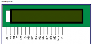
Interfacing an Arduino microcontroller with an LCD display consists of two parts, wiring and programming. A typical LCD display consists of 16 pins that control various features of the screen. The Arduino microcontroller can output voltages of either 5 V or 3.3 V, so the LCD can be powered by wiring VSS and VDD to the ground and 5 V pins on the microcontroller. It is possible to adjust the contrast of the screen by wiring a variable resistor to V0 located at pin 3 on the screen. The figure shows the Pin details of the Arduino – LCD Interface. Figure 4.6 shows the Arduino – LCD Interface.
| PIN NO | Name | Function | Description |
| 1 | V SS | Power | GND |
| 2 | V DD | Power | +5 V |
| 3 | Vee | Contrast adj. | (-2)0+5V |
| 4 | RS | Command | Register Select |
| 5 | R/W | Command | Read/write |
| 6 | E | Command | Enable (Strobe) |
| 7 | D0 | I/O | Data LSB |
| 8 | D1 | I/O | Data |
| 9 | D2 | I/O | Data |
| 10 | D3 | I/O | Data |
| 11 | D4 | I/O | Data |
| 12 | D5 | I/O | Data |
| 13 | D6 | I/O | Data |
| 14 | D7 | I/O | Data MSB |
Table: LCD Pin Configuration
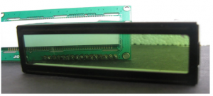
Display Glass
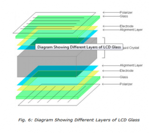 Glass Assembly
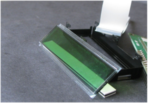
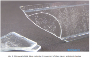
Polarizer & Liquid Crystal
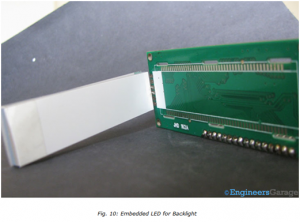
 Control Circuitry & Backlight
 Diffuser & PCB


