Piezo buzzer is an electronic device commonly used to produce sound. Light weight, simple construction and low price make it usable in various applications like car/truck reversing indicator, computers, call bells etc. Piezo buzzer is based on the inverse principle of piezo electricity discovered in 1880 by Jacques and Pierre Curie. It is the phenomena of generating electricity when mechanical pressure is applied to certain materials and the vice versa is also true. Such materials are called piezo electric materials. Piezo electric materials are either naturally available or manmade. Piezoceramic is class of manmade material, which poses piezo electric effect and is widely used to make disc, the heart of piezo buzzer. When subjected to an alternating electric field they stretch or compress, in accordance with the frequency of the signal thereby producing sound.
 At the heart of all piezo-type buzzers is the piezoelectric element. The piezoelectric element is composed of a piezoelectric ceramic and a metal plate held together with adhesive. Both sides of the piezoelectric ceramic plate contain an electrode for electrical conduction. Piezo materials exhibit a specific phenomenon known as the piezoelectric effect and the reverse piezoelectric effect. Exposure to mechanical strain will cause the material to develop an electric field, and vice versa.
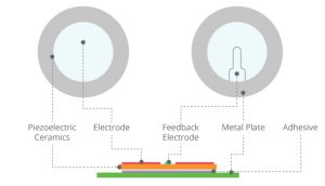
Working Principle of Piezo Buzzers
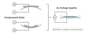
When an alternating voltage is applied to the piezoceramic element, the element extends and shrinks diametrically. This characteristic of piezoelectric material is utilized to make the ceramic plate vibrate rapidly to generate sound waves.
Piezo Buzzer Structure
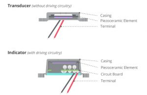
There are two types of piezo buzzers – transducers and indicators. Transducers consist of a casing, a piezo-ceramic element and a terminal. In order to operate a transducer, the user must send a square wave signal to the buzzer. Indicators consist of a casing, a piezoceramic element, a circuit board and a terminal. In order to operate an indicator, the user must send the buzzer a specified dc voltage.
Electronic Components.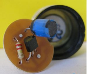
Fig. 4: Electronic Components behind PCB of Piezo Buzzer
This is the opposite side of the PCB, having the necessary electronic components: a resistor, a transistor and an inductor. The input to the transducer is a low voltage DC signal, however in order to produce sound the piezo-ceramic disc needs oscillations of high voltage. The transistor and resistor combination works as an oscillator circuit to produce low amplitude oscillations from the DC voltage. The magnitude of these oscillations is amplified by the inductor.
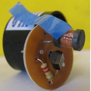
Fig. 5: Image Indicating Inductor Coil of PCB
Diaphragm
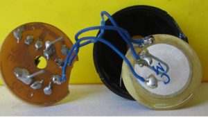
Fig. Image showing Diaphragm Attached to PCB—the Arrangement that Produces Sound
The above image shows the circular shaped diaphragm connected to the rest of the electronic components which is the source of producing sound. It consists of a metal plate made up of brass or stainless steel and a piezo-ceramic disc (white colored disc) of smaller radius connected to each other with a conductive adhesive. The metal plate is used because the resonance frequency of the piezo-ceramic material is too high to produce audible sound
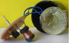
Fig. Metal Plate at Backside of Diaphragm
Piezo-ceramic Disc
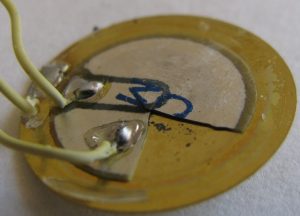
Fig. Close-up Image of Piezoceramic Disc, Attached Metal Plate, and Wire Connections
The above image is a clear view of the piezo-ceramic disc glued to the metal plate (a small segment of the piezo-ceramic disc has been removed for proper understanding). The piezo-ceramic disc is coated by electrodes on both sides. There are three wires connected to the diaphragm: one to the metal plate and one each to the electrodes of the ceramic material. The wire connected to the metal plate is grounded. One electrode is used to provide the high amplitude oscillation signals to the ceramic disc and the second is used to provide a feedback to the oscillating circuit.

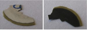
Fig. (Top left) Metal Disc with Piezoceramic Material Glued, (Top right) Metal disc, (Bottom left) Top of Metal Disc, (bottom right) Backside of Metal Disc
The above images in sequence shows the metal disc with piezo-ceramic material pasted on it , the metal disc, the front side of the piezo-ceramic disc, the backside of the piezo-ceramic disc.
Working:
When a small DC voltage is applied to the input pins, it is first converted to an oscillating signal using the combination of resistor and transistor. These oscillating signals are amplified using the inductor coil. When high voltage alternating signals are applied to the piezo-ceramic disc, it causes mechanical expansion and contraction in radial direction. This causes the metal plate to bend in opposite direction. When metal plate bends and shrinks in opposite direction continuously it produces sound waves in the air.


