Changing the Mode of Operation of Pins:
pinMode(pin, mode)
Used in void setup() to configure a specified pin to behave either as an INPUT or an OUTPUT.
pinMode(pin, OUTPUT); // sets ‘pin’ to output
Arduino digital pins default to inputs, so they don’t need to be explicitly declared as inputs with pinMode(). Pins configured as INPUT are said to be in a high-impedance state.
There are also convenient 20K pull-up resistors built into the Atmega chip that can be accessed from software. These built-in pullup resistors are accessed in the following manner:
pinMode(pin, INPUT); // set ‘pin’ to input
digitalWrite(pin, HIGH); // turn on pull up resistors
Pull-up resistors would normally be used for connecting inputs like switches Notice in the above example it does not convert pin to an output, it is merely a method for activating the internal pull-ups.
Pins configured as OUTPUT are said to be in a low-impedance state and can provide 40 mA (milliamps) of current to other devices/circuits. This is enough current to brightly light up an LED (don’t forget the series resistor), but not enough current to run most relays, solenoids, or motors.
Short circuits on Arduino pins and excessive current can damage or destroy the output pin, or damage the entire Atmega chip. It is often a good idea to connect an OUTPUT pin to an external device in series with a 4700 or 1K resistor
For a Real-time Arduino project visit our Videos at the below link:
Access the Values from Digital Pins:
digitalRead(pin)
Reads the value from a specified digital pin with the result either HIGH or LOW. The pin can be specified as either a variable or constant (0-13).
value = digitalRead(Pin); // sets ‘value’ equal to the input pin
digitalWrite(pin, value)
Outputs either logic level HIGH or LOW at turns on or off) a specified digital pin.The pin can be specified as either a variable or constant (0-13).
digitalWrite(pin, HIGH); // sets ‘pin’ to high
The following example reads a pushbutton connected to a digital input and tums on an LED connected to a digital output when the button has been pressed:
int led = 13; //connect LED to pin 13
int pin = 7; //connect pushbutton to pin 7
int value = 0; //variable to store the read value
void setup()
{
pinMode(led, OUTPUT); //sets pin 13 as output
pinMode(pin, INPUT); //sets pin 7 as input
}
void loop()
{
value = digitalRead(pin); //sets ‘value’ equal to the input pin
digitalWrite(led, value); //sets led to the
} //button’s value
Access the Values from Analog Pins:
analogRead(pin)
Reads the value from a specified analog pin with a 10-bit resolution. This function only works on the analog in pins (0-5). The resulting integer values range from 0 to 1023.
value = analogRead(pin); // sets ‘value’ equal to ‘pin’
Note: Analog pins unlike digital ones, do not need to be first declared as INPUT nor OUTPUT
analogWrite(pin, value)
Writes a pseudo-analog value using hardware-enabled pulse width modulation (PWM) to an output pin marked PWM. On newer Arduinos with the ATmega168 chip, this function works on pins 3, 5, 6, 9, 10, and 11. Older Arduinos with an ATmega8 only support pins 9. 10. and 11. The value can be specified as a variable or constant with a value from 0-255.
analogWrite(pin, value); // writes ‘value’ to analog ‘pin’
A value of 0 generates a steady O volts output at the specified pin: a value of 255 generates a steady 5 volts output at the specified pin. For values in between 0 and 255, the pin rapidly alternates between 0 and 5 volts – the higher the value, the more often the pin is HIGH (5 volts).
For example, a value of 64 will be 0 volts three-quarters of the time, and 5 volts one quarter of the time; a value of 128 will be at O half the time and 255 half the time, and a value of 192will be 0 volts one quarter of the time and 5 volts three-quarters of the time.
Because this is a hardware function, the pin will generate a steady wave after a call to analogWrite in the background until the next call to analogWrite (or a call to digitalRead or digitalWrite on the same pin).
Note: Analog pins unlike digital ones, do not need to be first declared as INPUT nor OUTPUT
The following example reads an analog value from an analog input pin, converts the value by dividing by 4, and outputs a PWM signal on a PWM pin:
int led = 10; // LED with 220 resistor on pin 10
int pin = 0; // potentiometer on analog pin
int value; // value for reading
void setup(){} // no setup needed
void loop()
{
value = analogRead(pin); // sets ‘value’ equal to ‘pin’
value /= 4; // converts – 1023 to 0-255
analogWrite(led, value); // outputs PWM signal to led
}
Time Related Functions:
delay(ms)
Pauses your program for the amount of time as specified in milliseconds, where 1000 equals 1 second.
delay(1000); // waits for one second
millis()
Returns the number of milliseconds since the Arduino board began running the current program as an unsigned long value.
value = millis(); // sets ‘value’ equal to millis()
Note: This number will overflow (reset back to zero), after approximately 9hours.
Some Math Functions:
min(x, y)
Calculates the minimum of two numbers of any data type and returns the smaller number.
value = min(value, 100); // sets ‘value’ to the smaller of ‘’value’ or 100, ensuring that
// it never gets above 100.
max(x, y)
Calculates the maximum of two numbers of any data type and returns the larger number.
value = max(value, 100); // sets ‘value’ to the larger of ‘value’ or 100, ensuring that
// it is at least 100.
Random Values Handling:
random Seed(seed)
Sets a value, or seed, as the starting point for the random() function.
randomSeed (value); // sets ‘value’ as the random seed
Because the Arduino is unable to create a truly random number, random Seed allows you to place a variable, constant, or other function into the random function, which helps to generate more random “random” numbers. There are a variety of different seeds or functions, that can be used in this function including millis() or even analogRead() to read electrical noise through an analog pin.
random(max)
random(min, max)
The random function allows you to return pseudo-random numbers within a range specified by min and max values.
value = random(100, 200); // sets ‘value’ to a random number between 100-200
Note: Use this after using the random Seed() function.
The following example creates a random value between 0-255 and outputs a PWM signal on a PWM pin equal to the random value:
int randNumber; // variable to store the random value
int led = 10; // LED with 220 resistor on pin 10
void setup() {} // no setup needed
void loop()
{
randomSeed (millis()); // sets millis() as seed
randNumber = random (255); // random number from 0-255
analogWrite(led, randNumber); // outputs PWM signal
delay(500); // pauses for half a second
}
Serial Data Communication:
Hundreds of communication protocols have been defined to achieve this data exchange. Each protocol can be categorized into one of the two categories: parallel or serial.
Parallel Communication
The parallel connection between the Arduino and peripherals via input/output ports is the ideal solution for shorter distances up to several meters. However, in other cases when it is necessary to establish communication between two devices for longer distances it is not possible to use the parallel connection. Parallel interfaces transfer multiple bits at the same time. They usually require buses of data – transmitting across eight, sixteen, or more wires. Data is transferred in huge, crashing waves of 1’s and 0’s.

Advantages and Drawbacks of Parallel Communication
Parallel communication certainly has its advantages. It is faster than serial, straightforward, and relatively easy to implement. However, it requires many input/output (I/O) ports and lines. If you have ever had to move a project from a basic Arduino Uno to a Mega, you know that the I/O lines on a microprocessor can be precious and few. Therefore, we prefer serial communication, sacrificing potential speed for pin real estate.
Serial Communication Modules
Today, most Arduino boards are built with several different systems for serial communication as standard equipment.
Which of these systems are used depends on the following factors –
- How many devices the microcontroller has to exchange data with?
- How fast the data exchange has to be?
- What is the distance between these devices?
Is it necessary to send and receive data simultaneously?
One of the most important things concerning serial communication is the Protocol, which should be strictly observed. It is a set of rules, which must be applied such that the devices can correctly interpret data they mutually exchange. Fortunately, Arduino automatically takes care of this, so that the work of the programmer/user is reduced to simple write (data to be sent) and read (received data).
Types of Serial Communications
Serial communication can be further classified as –
- Synchronous – Devices that are synchronized use the same clock and their timing is in synchronization with each other.
- Asynchronous – Devices that are asynchronous have their own clocks and are triggered by the output of the previous state.
It is easy to find out if a device is synchronous or not. If the same clock is given to all the connected devices, then they are synchronous. If there is no clock line, it is asynchronous.
For example, UART (Universal Asynchronous Receiver Transmitter) module is asynchronous. The asynchronous serial protocol has a number of built-in rules. These rules are nothing but mechanisms that help ensure robust and error-free data transfers. These mechanisms, which we get for eschewing the external clock signal, are:
- Synchronization bits
- Data bits
- Parity bits
- Baud rate
Synchronization Bits
The synchronization bits are two or three special bits transferred with each packet of data. They are the start bit and the stop bit(s). True to their name, these bits mark the beginning and the end of a packet respectively. There is always only one start bit, but the number of stop bits is configurable to either one or two (though it is normally left at one). The start bit is always indicated by an idle data line going from 1 to 0, while the stop bit(s) will transition back to the idle state by holding the line at 1.
 Data Bits
The amount of data in each packet can be set to any size from 5 to 9 bits. Certainly, the standard data size is your basic 8-bit byte, but other sizes have their uses. A 7-bit data packet can be more efficient than an 8, especially if you are just transferring 7-bit ASCII characters.
Parity Bits
The user can select whether there should be a parity bit or not, and if yes, whether the parity should be odd or even. The parity bit is 0 if the number of 1’s among the data bits is even. Odd parity is just the opposite.
Baud Rate
The term baud rate is used to denote the number of bits transferred per second [bps]. Note that it refers to bits, not bytes. It is usually required by the protocol that each byte be transferred along with several control bits. It means that one byte in the serial data stream may consist of 11 bits. For example, if the baud rate is 300 bps then a maximum of 37 and a minimum of 27 bytes may be transferred per second. Arduino UART
The following code will make Arduino send hello world when it starts up.

After the Arduino sketch has been uploaded to Arduino, open the Serial monitor at the top right section of Arduino IDE.
Type anything into the top box of the Serial Monitor and press send or enter on your keyboard. This will send a series of bytes to the Arduino.
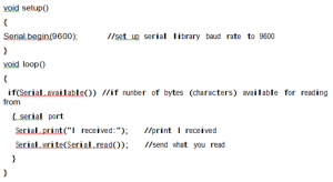
The following code returns whatever it receives as an input.
The following code will make Arduino deliver output depending on the input provided.

Notice that Serial.print and Serial.println will send back the actual ASCII code, whereas
Serial.write will send back the actual text. See ASCII codes for more information.
Serial.begin(rate)
Opens serial port and sets the baud rate for serial data transmission. The typical baud rate for communicating with the computer is 9600 although other speeds are supported.
void setup()
{
Serial.begin(9600); // opens serial port
} // sets data rate to 9600 bps
Note: When using serial communication, digital pins 0 (RX) and 1 (TX) cannot be used at the same time.
Serial.println(data)
Prints data to the serial port, followed by an automatic carriage return and line feed. This command takes the same form as Serial.print(), but is easier for reading data on the Serial Monitor.
Serial.println(analogValue); // sends the value of ‘analogValue
Note: For more information on the various permutations of the Serial.println()and Serial.print() functions please refer to the Arduino website.
The following simple example takes a reading from analog pino and sends this data to the computer every 1 second.
void setup()
{
Serial.begin(9600); // sets serial to 9600bps
}
void loop()
{
Serial.println(analogRead()); // sends analog value
delay(1000); // pauses for 1 second
}
Digital Output

This is the basic ‘hello world’ program used to simply turn something on or off. In this example, an LED is connected to pin 13 and is blinked every second. The resistor may be omitted on this pin since the Arduino has one built-in.
int ledPin = 13; // LED on digital pin 13
void setup() // run once
{ // sets pin 13 as output
pinMode(ledPin, OUTPUT);
}
void loop() // run over and over again
{
digitalWrite(ledPin, HIGH); // turns the LED on
delay(1000); // pauses for 1 second
digitalWrite(ledPin, LOW); // turns the LED off
delay(1000); // pauses for 1 second
}
For Real-time Arduino Project examples go through our Video below:
Digital Input

This is the simplest form of input with only two possible states: on or off. This example reads a simple switch or pushbutton connected to pin2. When the switch is closed the input pin will read HIGH and turn on an LED.
int ledPin = 13; // output pin for the LED
int inPin = 2; // input pin (for a switch)
void setup()
{
pinMode(ledPin, OUTPUT); // declare LED as output
pinMode(inPin, INPUT); // declare switch as input
}
void loop()
{
if (digitalRead(inPin) == HIGH) // check if input is HIGH
{
digitalWrite(ledPin, HIGH); // turns the LED on
delay(1000); // pause for 1 second
digitalWrite(ledPin, LOW); // turns the LED off
delay(1000); // pause for 1 second
}
}
High Current Output

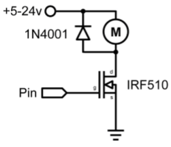
Sometimes it is necessary to control more than 40ma from the Arduino. In this case, a MOSFET or transistor could be used to switch higher current loads. The following example quickly turns on and off the MOSFET 5 times every second.
Note: The schematic shows a motor and protection diode but other non-inductive loads could be used without the diode.
int outpin= 5; // output pin for the MOSFET
void setup()
{
pinMode(outPin, OUTPUT); // sets pin5 as output
}
void loop()
{
for (int i=0; i<=5; i++) // loops 5 times
{
digitalWrite(outPin, HIGH); // turns MOSFET on
delay(250); // pauses 1/4 second
digitalWrite(outPin, LOW); // turns MOSFET off
delay(250); // pauses 1/4 second
}
delay(1000); // pauses 1 second
}
PWM Output

Pulse Width Modulation (PWM) is a way to fake an analog output by pulsing the output. This could be used to dim and brighten an LED or later to control a servo motor. The following example slowly brightens and dims an LED using for loops.
int ledPin = 9; // PWM pin for the LED
void setup() {} // no setup needed
void loop()
{
for (int i=0; i<=255; i++) // ascending value for i
{
analogWrite(ledPin, i); // sets brightess level to i
delay(100); // pauses for 100ms
}
for (int i=255; i>=0; i–) //descending value for i
{
analogWrite(ledPin, i); // sets brightess level to i
delay(100); // pauses for 100ms
}
}
Potentiometer Input

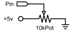
Using a potentiometer and one of Arduino’s analog-to-digital conversion (ADC) pins it is possible to read analog values from 0-1024. The following example uses a potentiometer to control an LED’s rate of blinking.
int potPin = 0; // input pin for the potentiometer
int ledPin = 13; // output pin for the LED
void setup()
{
pinMode(ledPin, OUTPUT); // declare ledPin as OUTPUT
}
void loop()
{
digitalWrite(ledPin, HIGH); // turns ledPin on
delay(analogRead(potPin)); // pause program
digitalWrite(ledPin, LOW); // turns ledPin off
delay (analogRead(potPin)); // pause program
}
Variable Resistor Input

Variable resistors include CdS light sensors, thermistors, flex sensors, and so on. This example makes use of a function to read the analog value and set a delay time. This controls the speed at which an LED brightens and dims.
int ledPin =9; // PWM pin for the LED
int analogPin =0; // variable resistor on analog pin o
void setup() // no setup needed
void loop()
{
for (int i=0; i<=255; i++) // ascending value for i
{
analogWrite(ledPin, i); // sets brightess level to i
delay(delayVal(); // gets time value and pauses
}
for (int i=255; i>=0; i–) // descending value for i
{
analogWrite(ledPin, i); // sets brightess level to i
delay (delayVal()); // gets time value and pauses
}
}
int delayval()
{
int v; // create temporary variable
V = analogRead(analogPin); // read analog value
V = 8; // convert 0-1024 to 0-128
return v; // returns final value
}
Servo Output
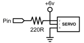
Hobby servos are a type of self-contained motor that can move in a 180° arc. All that is needed is a pulse sent every 20ms. This example uses a servo pulse function to move the servo from 10°-170° and back again.
int servoPin = 2; // servo connected to digital pin 2
int myAngle; // angle of the servo roughly 0-180
int pulseWidth; // servoPulse function variable
void setup()
{
pinMode(servoPin, OUTPUT); // sets pin 2 as output
}
void servoPulse(int servoPin, int myAngle)
{
pulseWidth = (myAngle * 10) + 600; // determines delay
digitalWrite(servoPin, HIGH); // set servo high
delayMicroseconds (pulseWidth); // microsecond pause
digitalWrite(servoPin, LOW); // set servo low
}
void loop()
{
// servo starts at 10 deg and rotates to 170 deg
for (my Angle=10; myAngle<=170; myAngle++)
{
servoPulse (servoPin, myAngle); // send pin and angle
delay(20); // refresh cycle
}
// servo starts at 170 deg and rotates to 10 deg
for (myAngle=170; myAngle>=10; myAngle)
{
servoPulse (servoPin, myAngle); // send pin and angle
delay(20); // refresh cycle
}
}
For a Real-time Arduino project visit our Videos at the below link:


