TSOP 1738 IR Receiver
TSOP17XX is a commonly used IR receiver for Infrared PCM remote control systems. It is used in TVs, DVD Players, Burglar Alarms, etc. This component is built with PIN Diode, Preamplifier and internal filter for PCM (Pulse Code Modulation) frequency, and its epoxy package is designed as an IR filter. These are available with different carrier frequencies out of which TSOP 1738 is an IR Receiver for IR (Infrared) remote controls. It consists of Photo Detector, Gain Control, Band Pass Filter, Demodulator, and a Preamplifier in a single package. TSOP17XX series of IR Receivers are very common for all types of transmission codes supporting different modulating techniques like RC6, RC5, NEC, Sony, etc.
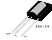
TSOP 1738 in particular supports a carrier frequency of 38 kHz and the output of this IR Receiver can be directly connected to a microcontroller or a microprocessor. TSOP 1738 has three pins namely GND, VS, and OUT. The following image shows the pinout of TSOP 1738.

Some of the other characteristics of TSOP 1738 are high immunity to ambient light, active low output, low power consumption, continuous data transmission, and compatibility with TTL as well as CMOS. A typical application circuit of TSOP 1738 IR Receiver (or any IR Receiver for that matter) will consist of an IR Transmitter (IR LED), IR Receiver (TSOP 1738), and a microcontroller. The following image describes the block diagram of the IR Transmitter and Receiver. In the image, the IR Transmitter emits Infrared light modulated at a particular frequency. The IR Receiver will receive this modulated signal and demodulates it and sends it to the Microcontroller.
Block Diagram

TSOP17XX are provided with Band Pass Filter, Automatic Gain Control (AGC), and Integrator to avoid changes in output due to noises or other disturbances. Noises and Data signals are distinguished by using carrier frequency, burst length, and duty cycle. Data Signals should satisfy the following conditions.
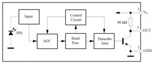
TSOP module has an inbuilt control circuit for amplifying the coded pulses from the IR transmitter. A signal is generated when the PIN photodiode receives the signals. This input signal is received by an automatic gain control (AGC). For a range of inputs, the output is fed back to AGC in order to adjust the gain to a suitable level. The signal from AGC is passed to a bandpass filter to filter undesired frequencies. After this, the signal goes to a demodulator and this demodulated output drives an NPN transistor. The collector output of the transistor is obtained at pin 3 of the TSOP module.
Members of the TSOP17xx series are sensitive to different center frequencies of the IR spectrum. For example, TSOP1738 is sensitive to 38 kHz whereas TSOP1740 to 40 kHz center frequency.
The carrier frequency of the received signal should be close to the center frequency of the bandpass filter of the device. For eg: Carrier frequency should be close to 38KHz for TSOP1738.
Burst Length should be longer than or equal to 10 cycles/burst and lesser than or equal to 70 cycles/burst.
A gap time of at least 14 cycles is necessary after each burst.
A gap of at least the same length as the burst is necessary at some point in the data stream for bursts longer than 1.8ms.
It can receive up to 1400 short bursts continuously.

From the image, it can be observed that the output of the IR Receiver is directly connected to the Microcontroller and there is no need for any extra interface. Also, Resistor R and Capacitor C are only used to suppress the power supply disturbances. Lights coming from sunlight, fluorescent lamps, etc. may cause disturbance to it and result in undesirable output even when the source is not transmitting IR signals. A bandpass filter, an integrator stage, and automatic gain control are used to suppress such disturbances.
Features
- Photo Detector, IR Filter, Preamplifier, and PCM frequency filter in one package
- Shielding against EMI or RFI interference
- CMOS and TTL Compatible
- Active Low Output
- Immunity against ambient light
- Low Power Consumption
- Able to transfer data continuously up to 2400bps
- Supply Voltage: 4.5 – 5.5V
RF Transmitter & Receiver
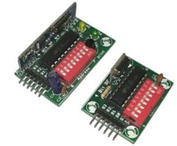
The TX is an ASK transmitter module. The TX is designed specifically for remote-control, wireless mouse, and car alarm systems operating at 315/433.92 MHz.The RX is a miniature receiver module that receives On-ff keyed (OOK)modulation signal and is demodulated to a digital signal for the next decoder stage. The RX is designed specifically for remote-control and wireless security receivers operating at 315/434Mhz. UART TTL o/p -Baud Rate -9600. Basically, the RF modules are 433 MHz RF transmitter and receiver modules. The transmitter draws no power when transmitting logic zero while fully suppressing the carrier frequency thus consuming significantly low power in battery operation. When logic one is sent carrier is fully on to about 4.5mA with a 3volts power supply. The data is sent serially from the transmitter which is received by the tuned receiver. The transmitter and the receiver are duly interfaced to two microcontrollers for data transfer.
 The RF module
RF module is often used along with a pair of encoders/decoders. The encoder is used for encoding parallel data for transmission feed while the reception is decoded by a decoder. This little module is a transmitter among the two. It is really simple as it looks. The heart of the module is the SAW resonator which is tuned for 433.xx MHz operation. There is a switching transistor and a few passive components, that’s it. When a logic HIGH is applied to the DATA input, the oscillator runs producing a constant RF output carrier wave at 433.xx MHz and when the DATA input is taken to logic LOW, the oscillator stops. This technique is known as Amplitude Shift Keying, which we will discuss in detail shortly.

This one is a receiver module. Though it looks complex, it is as simple as the transmitter module. It consists of an RF tuned circuit and a couple of OP Amps to amplify the received carrier wave from the transmitter. The amplified signal is further fed to a PLL (Phase Lock Loop) which enables the decoder to “lock” onto a stream of digital bits which gives better-decoded output and noise immunity.

ASK – Amplitude Shift Keying
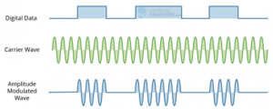
As discussed above, for sending the digital data over the radio, these modules use a technique called Amplitude Shift Keying or ASK. In Amplitude Shift Keying the amplitude (i.e. the level) of the carrier wave (in our case it’s a 433MHz signal) is changed in response to the incoming data signal. This is very similar to the analog technique of amplitude modulation which you might be familiar with if you’re familiar with AM radio. It’s sometimes called binary amplitude shift keying because there are only two levels we are concerned with. You can think of it as an ON/OFF switch.
- For Digital 1 – This drives the carrier at full strength.
- For Digital 0 – This cuts the carrier off completely.
This is what the Amplitude modulation looks like:

Amplitude Shift keying has the advantage of being very simple to implement. It is quite simple to design the decoder circuitry. Also, ASK needs less bandwidth than other modulation techniques like FSK (Frequency Shift Keying). This is one of the reasons for being inexpensive. The disadvantage however is that ASK is susceptible to interference from other radio devices and background noise. But as long as you keep your data transmission to a relatively slow speed it can work reliably in most environments.
Features of RF Module:
- Receiver frequency 433MHz
- Receiver typical frequency 105Dbm
- Receiver supply current 3.5mA
- Low power consumption
- Receiver operating voltage 5v
- Transmitter frequency range 433.92MHz
- Transmitter supply voltage 3v~6v
- Transmitter output power 4v~12v
Main Factors Affecting RF Module’s Performance:
As compared to the other radio-frequency devices, the performance of an RF module will depend on several factors by increasing the transmitter’s power a large communication distance will be gathered. However, which will result in a high electrical power drain on the transmitter device, which causes shorter operating life of the battery-powered devices. Also using this device at higher transmitted power will create interference with other RF devices.
Applications:
- Wireless security systems
- Car alarm systems
- Remote controls
- Sensor reporting
- Automation systems


