STEPPER MOTOR

Introduction to Stepper Motors
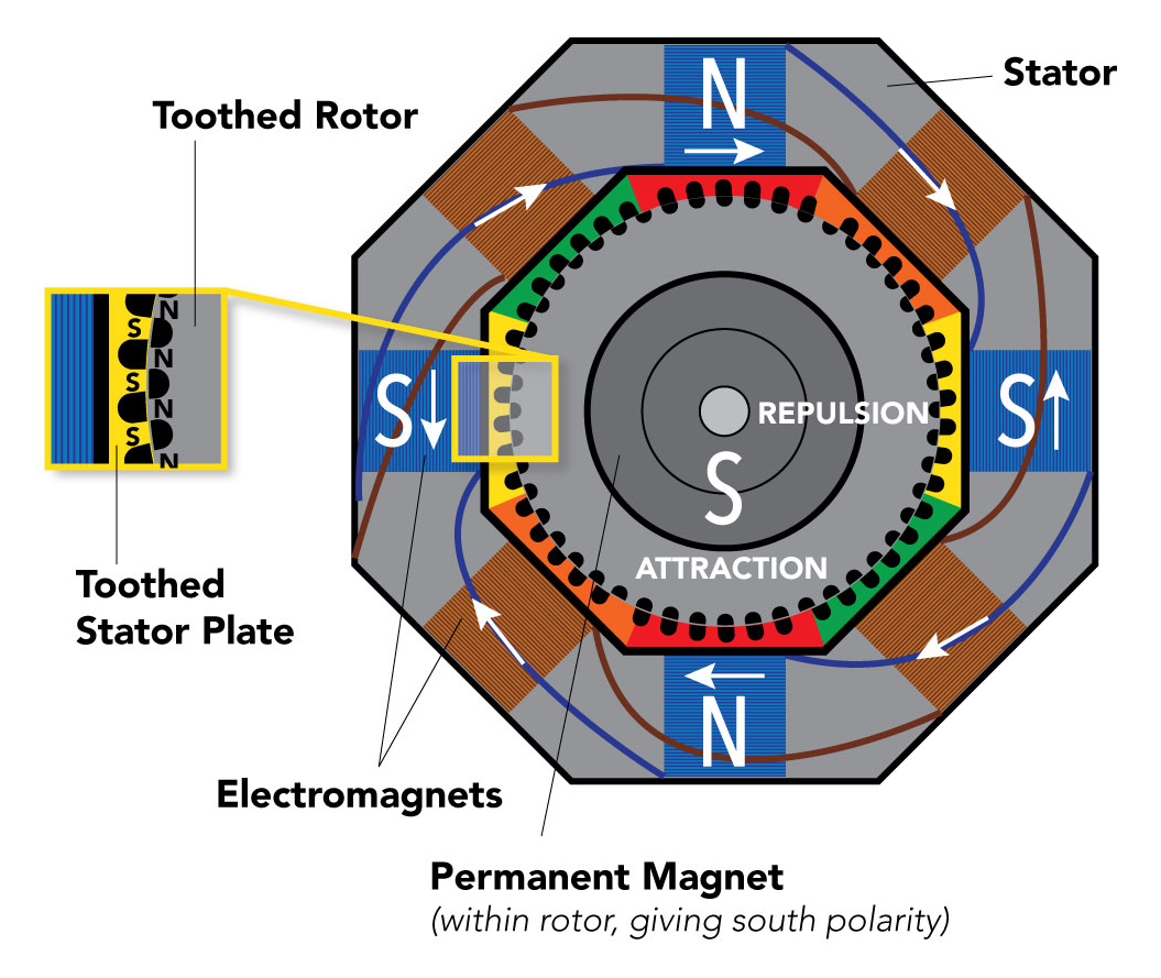
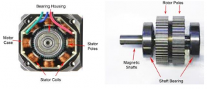
Like all motors, the stepper motors also have a stator and a rotor, but unlike a normal DC motor, the stator consists of individual sets of coils. The number of coils will differ based on the type of stepper motor, but for now, just understand that in a stepper motor the rotor consists of metal poles and each pole will be attracted by a set of coils in the stator. The below diagram shows a stepper motor with 8 stator poles and 6 rotor poles.
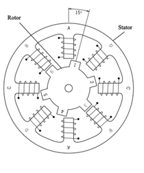
If you take a look at the coils on the stator, they are arranged in terms of coil pairs, like A and A’ forms a pair B and B’ forms a pair, and so on. So each of these coil pairs forms an electromagnet and they can be energized individually using a driver circuitry. When a coil gets energized it acts as a magnet and the rotor pole gets aligned to it, when the rotor rotates to adjust itself to align with the stator it is called one step. Similarly, by energizing the coils in a sequence we can rotate the motor in small steps to make a complete rotation.
Types of stepper motors
There are mainly three types of stepper motors based on construction, which are:
- Variable reluctance stepper motor: They have an iron core rotor that is attracted towards the stator poles and provides movement by minimum reluctance between stator and rotor.
- Permanent magnet stepper motor: They have a permanent magnet rotor and they are repelled or attracted towards the stator according to pulses applied.
- Hybrid synchronous stepper motor: They are the combination of Variable reluctance and permanent magnet stepper motor.
Apart from this, we can also classify the stepper motors as Unipolar and Bipolar based on the type of stator winding.
Bipolar Stepper Motor:
The stator coils on this type of motor will not have a common wire. The driving of this type of stepper motor is different and complex and also the driving circuit cannot be easily designed without a microcontroller.
Unipolar Stepper Motor:
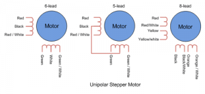
In this type of stepper motor, we can take the center tapping of both the phase windings for common ground or for a common power as shown below. This makes it easy to drive the motors, there are many types of Unipolar stepper motors as well.
Modes of operation in Stepper Motor
Since the stator of the stepper mode is built of different pairs of coils, each coil pair can be excited in many different methods, thus enabling the modes to be driven in many different modes. The following are the broad classifications
Full Step Mode
In full-step excitation mode, we can achieve a full 360° rotation with a minimum number of turns (steps). But this leads to less inertia and also the rotation will not be smooth. There are further two classifications in Full Step Excitation, they are one Phase-on wave stepping and two phase-on modes.
One phase-on stepping or Wave Stepping:
In this mode, only one terminal (phase) of the motor will be energized at any given time. This has less number of steps and hence can achieve a full 360° rotation. Since the number of steps is less the current consumed by this method is also very low. The following table shows the wave stepping sequence for a 4 phase stepper motor.
 Two Phase-on steppings:
As the name states in this method, two phases will be one. It has the same number of steps as Wave stepping, but since two coils are energized at a time it can provide better torque and speed compared to the previous method. Although one downside is that this method also consumes more power.
 Half Step Mode
The Half Step mode is the combination of one phase-on and two-phase on modes. This combination will help us to get over the above-mentioned disadvantage of both modes.
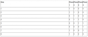
As you might have guessed since we are combining both the methods we will have to perform 8-steps in this method to get a complete rotation. The switching sequence for a 4-phase stepper motor is shown below
Micro Step Mode
Micro-stepping mode is the most complex of all, but it offers very good precision along with good torque and smooth operation. In this method, the coil will be excited with two sine waves that are 90° apart. This way we can control both the direction and amplitude of the current flowing through the coil which helps us to increase the number of steps the motor has to make for one complete rotation. Micro stepping can take as high as 256 steps to make one complete rotation, this makes the motor rotate faster and smoother.
These motors are used in two varieties, namely unipolar/bipolar. Bipolar motors are the most solid type of motor and generally have 4 or 8 leads. They have two arrays of electromagnetic coils inside, and stepping is attained by altering the current direction in the coils. Unipolar motors are recognizable by having 5 wires, 6 wires or even 8 wires, also have 2-coils, but each one has a center tap. These motors can step without having to the opposite direction of current in the coils, making the electronics simpler. But, because this tap is used to strengthen only half of each coil at a time they normally have less torque than bipolar.
The stepper motor design can give a constant holding torque without the necessity of the activated motor, provided that the motor is used inside its limits, placing errors doesn’t occur, since these motors have bodily pre-defined situations.
How to use a Stepper Motor
Enough of boring theory, let’s assume someone gives you a stepper motor say the famous 28-BYJ48 and you are really curious to make it work. By this time you would have understood that it is not possible to make these motors rotate by just powering them through a supply, so how would you do it?
Let us take a look at this 28-BYJ48 Stepper motor.
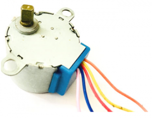
Okay, so unlike a normal DC motor this one has five wires of all fancy colors coming out of it and why is it so? To understand this we should first know how a stepper which we already discussed. First of all steppers motors do not rotate, they step and so they are also known as step motors. Meaning, they will move only one step at a time. These motors have a sequence of coils present in them and these coils have to be energized in a particular fashion to make the motor rotate. When each coil is being energized the motor takes a step and a sequence of energization will make the motor take continuous steps, thus making it rotate. Let us take a look at the coils present inside the motor to know exactly know from where these wires come from.

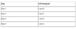
As you can see the motor has a unipolar 5-lead coil arrangement. There are four coils that have to be energized in a particular sequence. The Red wires will be supplied with +5V and the remaining four wires will be pulled to the ground for triggering the respective coil. We use any microcontroller to energize these coils in a particular sequence and make the motor perform the required number of steps. Again there are many sequences you can use, normally a 4-step is used and for more precise control an 8-step control can also be used. The sequence table for the 4-step control is shown below.
Calculating the Steps per Revolution for Stepper Motor
It is important to know how to calculate the steps per Revolution for your stepper motor because only then you can program/drive it effectively.
Let us assume we will be operating the motor in a 4-step sequence so the stride angle will be 11.25° since it is 5.625°(given in datasheet) for 8 step sequence, it will be 11.25° (5.625*2=11.25).
Steps per revolution = 360/step angleHere, 360/11.25 = 32 steps per revolution.
Why do we need Driver modules for Stepper Motors?
Most stepper motors will operate only with the help of a driver module. This is because the controller module (Microcontroller/Digital circuit) will not be able to provide enough current from its I/O pins for the motor to operate. So we will use an external module like the ULN2003 module as a stepper motor driver. There are many types of a driver modules and the rating of one will change based on the type of motor used. The primary principle for all driver modules will be to source/sink enough current for the motor to operate.
Advantages of Stepper Motor:
- The rotation angle of the motor is proportional to the input pulse.
- The motor has full torque at standstill.
- Precise positioning and repeatability of movement since good stepper motors have an accuracy of 3 – 5% of a step and this error are non-cumulative from one step to the next.
- Excellent response to starting, stopping, and reversing.
- Very reliable since there are no contact brushes in the motor. Therefore the life of the motor is simply dependent on the life of the bearing.
- The motor’s response to digital input pulses provides open-loop control, making the motor simpler and less costly to control.
- It is possible to achieve very low-speed synchronous rotation with a load that is directly coupled to the shaft.
- A wide range of rotational speeds can be realized as the speed is proportional to the frequency of the input pulses.
Applications:
- Industrial Machines – Stepper motors are used in automotive gauges and machine tooling automated production equipment.
- Security – new surveillance products for the security industry.
- Medical – Stepper motors are used inside medical scanners, samplers, and also found inside digital dental photography, fluid pumps, respirators, and blood analysis machinery.
- Consumer Electronics – Stepper motors in cameras for automatic digital camera focus and zoom functions.
Differences between Stepper Motor and Servo Motor:
- Stepper Motors have a large number of poles, magnetic pairs generated by a permanent magnet or an electric current. Servo motors have very few poles; each pole offers a natural stopping point for the motor shaft.
- The torque of a stepper motor at low speeds is greater than a servo motor of the same size.
- Stepper motor operation is synchronized by command pulse signals output from the pulse generator. In contrast, servomotor operation lags behind the command pulses.
Pros and Cons of DC, Servo, and Stepper Motor
The advantages and disadvantages of DC motor, servo motor, and stepper motor include the following.
- DC motors are fast and continuous rotation motors mainly used for anything that needs to rotate at a high rotation per minute (RPM). For instance; car wheels, fans, etc.
- Servo motors are high torque, fast, accurate rotation at a limited angle. Generally, a high-performance alternative to stepper motors, but a more complicated setup with PWM tuning. Suited for robotic arms/legs or rudder control etc.
- Stepper motors are slow, easy setup, precise rotation, and control – Advantage over other motors like servo motors in controlling of a position. Where these motors require a feedback mechanism and backing circuitry to drive locating, this motor has positional control through its nature of rotation by fractional additions. Suitable for 3D printers and related devices where the position is essential.

