Breadboard Basics
In the 1960s, wire-wrap technique is used for designing, building, and testing the electronic circuits and prototypes. Then, the larger boards (like wooden boards used for bread slicing) were used onto which the components (huge electronics elements) were connected using wires, pins or thumbtacks. Hence, these are called as breadboards but, technical name of these circuit boards is solderless breadboards. These solderless breadboards consist of holes which are used for placing the component terminals and then these holes are connected to each other using various wires.
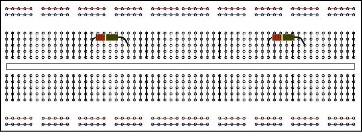
 Breadborad-Layout-Diagram
Breadboard Connections Basics
If we see breadboard for the first time, then we may feel it is very hard task to connect the circuit as it consist of several holes which are a bit confusing. In fact, it is very easy to connect the circuit if we understand the breadboard connections basics. The first two rows (top) and last two rows (bottom) of the breadboard are used for positive (one row of first and last two) and for negative (another row of first and last two).
Here, the first (top) and last (bottom) two rows of the breadboard consists of 5 holes in each column (totally 10 columns) are horizontally connected each other internally. If the power source terminal is connected in one hole of one column on top or bottom row (one of the two rows), then the same electric power can be taken from the successive five holes in the same column. The conductive layout diagram of the breadboard is shown in the figure above.
Breadboard Connections
Let us know breadboard connections basics such as how the rails are connected internally. The below figure shows the internal connections of component rails and power rails.
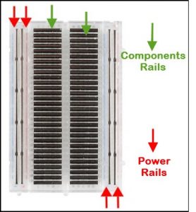
Breadboard Internal Diagram
In fact, the power rails can be connected by using jumper wires as shown in the figure below for obtaining same power supply in both the rails. Here, the terminal indications plus and minus are just for indication and there is no need for connecting power in “+” indicated rail and ground into the “-” indicated rail.
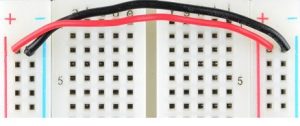
Connecting Power Rails using Jump Wires
The electronics beginners may get confused while connecting the DIP (Dual In-line Packages) components such as integrated circuits, microcontrollers, chips, etc.,. The rails are isolated by ravine or crevasse, thus the rows are not connected to each other on either side. So, the DIP components can be connected as shown in the figure below.
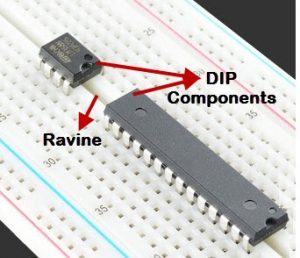
Connecting DIP Components on Breadboard
There are some binding posts along with breadboard which look like connected to breadboard internally. In fact, these are not connected and externally we can connect them using some jumper wires as per requirement.
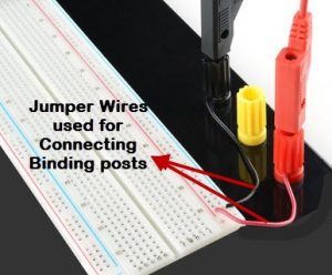
Connecting Binding Posts to Breadboard using Jumper Wires
There are various programs that can be used for building general circuits, electronics projects circuits, etc., on a virtual breadboard. These programs include Fritzing that facilitates the user to design the circuits and also to test the circuit functionality.

